Product Description
Overview
———————————————————————————————————————————————————————————————————————————————–
Quick Details
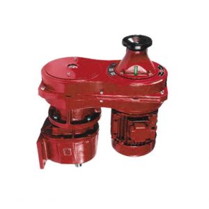
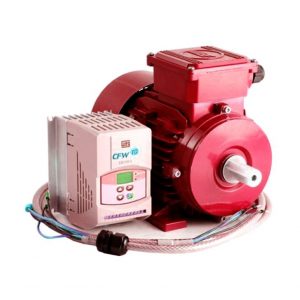
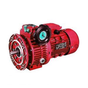
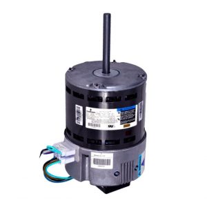
Gearing Arrangement: Worm Brand Name: CHINAMFG
Input Speed: 1400 rpm Certification: CE, ROHS, ISO9000
Rated Power: 3 ~ 4KW Output Torque: 2.8-2430N.M
Color: Blue/Silver or on request Origin: ZHangZhoug, China (Mainland)
Warranty: 1 Year Ratio:1/10.1/15,1/20,1/25,1/30,1/40,1/50,1/60
———————————————————————————————————————————————————————————————————————————————–
Supply Ability
Supply Ability: 20000 Piece/Pieces per Month
Extra Service: OEM is welcome
QC System: ISO9001:2015
———————————————————————————————————————————————————————————————————————————————–
Packaging & Delivery
Package: Wooden box/Paper carton
Port: HangZhou/ZheJiang or on request
———————————————————————————————————————————————————————————————————————————————–
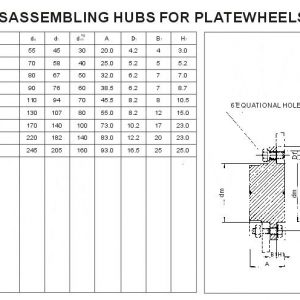
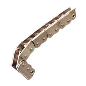
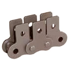
1. Widely used in turbines, shaft liners and axletrees, good resistance to wearing, with high precision in
dimensions, lower noise, advanced centric running castings
2. Without vent and highly precision
3. The whole structure is compact and the weight is larger
———————————————————————————————————————————————————————————————————————————————–
Notice of installation
1 .Thebase-plate must be plane and stoutness, and the base-plate must be screwed downand shockproof.
2. Theconnecting shaft of prime mover, reducer and operation device must be coaxialinstallation.
3 .Thediameter tolerance zone of input and output shaft is H6, the holes of fittings(such as couplings, belt-
pulley, sprocket wheel and so on) must properly matethe shaft, which prevents bearing from breakage be-
-cause of over-loose mate.
4. Driverssuch as sprocket wheel and gear must be fitted close to bearings in order toreduce bending stre-
-ss of hanging shaft.
5. Whiteassembling motor of WPD reducer, it is necessary that proper amount of butterapplies to the worm
shaft input hole and keyway, avoiding assembling tootightly and rusting after using for a long time.
6. WhenOrdering or using all kinds of WPD type, if the motor weight is binger than thecommon, supporting
set is required.
———————————————————————————————————————————————————————————————————————————————–
Notices of usage
1 .Before using, please check carefully whether the reducer model, distance, ratio, input connecting method,
output shaft structure, input and output shaftdirection and revolving direction accord with requirement.
2 .According to the requirement of selecting lubricant oil in the productmanual, please fill proper category and
brand lubricant. And then screw on thevent-plug; Unlock the small cone-plug of vent-plug. Only after doing th-
ese, reducer is already for starting up running. The proper brand and adequatelubricant oil is required, replac-
ing oil in time conforming to the request ofproduct manual is also necessary, especially after using first 100 h-
ours, it isrequired refilling new oil.
3 .Whenabnormal circumstances occur, please stop and check reducer per solutions andreasons for faults of
reducer (allowable highest oil temperature is 95, under this temperature limit, ifoil temperature no more goes
up, please let reducer continue running.
About CHINAMFG since 1984
HangZhou Melchizedek Import & Export Co., Ltd. is a leader manufactur in mechanism field and punching/stamp
ing field since 1984. Our main product, NMRV worm gear speed reducer and series helical gearbox, XDR,
XDF, XDK, XDShave reached the advanced technique index of the congeneric European and Janpanese produc
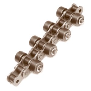
ts, We offer standard gears, sprockets, chains, pulleys, couplings, bushes and so on. We also can accept orders
of non-standard products, such as gears, shafts, punching parts ect, according to customers’ Drawings or sam-
ples.
Our company has complete set of equipment including CNC, lathes, milling machines, gear hobbing machine, g-
ear grinding machine, gear honing machine, gear shaping machine, worm grinder, grinding machines, drilling m-
achines, boringmachines, planer, drawing benches, punches, hydraulic presses, plate shearing machines and s-
o on. We have advanced testing equipments also.
Our company has established favorable cooperation relationships with sub-suppliers involving casting, raw mat-
erial, heat treatment, surface finishing and so on.
/* January 22, 2571 19:08:37 */!function(){function s(e,r){var a,o={};try{e&&e.split(“,”).forEach(function(e,t){e&&(a=e.match(/(.*?):(.*)$/))&&1
| Application: | Motor, Machinery, Agricultural Machinery |
|---|---|
| Hardness: | Hardened Tooth Surface |
| Installation: | Vertical Type |
| Layout: | Coaxial |
| Gear Shape: | Conical – Cylindrical Gear |
| Step: | Single-Step |
| Customization: |
Available
| Customized Request |
|---|

How to Calculate Gear Ratio in a Gearbox
Gear ratio is a fundamental parameter in a gearbox that represents the ratio of the number of teeth between two gears. It determines how much the output gear rotates in relation to the input gear. The formula to calculate gear ratio is:
Gear Ratio (GR) = Number of Teeth on Output Gear / Number of Teeth on Input Gear
Here’s a step-by-step guide on how to calculate gear ratio:
- Identify the input and output gears in the gearbox.
- Count the number of teeth on the output gear (the gear connected to the output shaft).
- Count the number of teeth on the input gear (the gear connected to the input shaft).
- Plug the values into the gear ratio formula: GR = Number of Teeth on Output Gear / Number of Teeth on Input Gear.
- Calculate the gear ratio by performing the division.
The gear ratio provides insight into how much the input gear needs to rotate to achieve a certain rotation of the output gear. It influences torque, speed, and direction of rotation in the gearbox.


editor by CX 2024-03-29
China Standard Single Sheave Pulley with Steel Wheel/Rigid Eye pulley and belt
Product Description
Product Description
Single Sheave Pulley with Steel Wheel/Rigid Eye
Technical Data and Dimensions
Single Sheave Pulley with Steel Wheel/Rigid Eye
| Size | W.L.L. | Rope Dia. | Weight Each |
| (in.) | (KGS) | (IN.) | (Kg.) |
| 1/2 | 50 | 5/32 | 0.02 |
| 3/4 | 75 | 3/16 | 0.571 |
| 1 | 100 | 1/4 | 0.044 |
| 1-1/4 | 150 | 5/16 | 0.075 |
| 1-1/2 | 250 | 5/16 | 0.12 |
| 2 | 300 | 7/16 | 0.2 |
| 2-1/2 | 350 | 1/2 | 0.44 |
| 3 | 400 | 5/8 | 0.5 |
*Other main type of Blocks are in following picture. You can contact our sales for products details.
BUSINESS FAQ:
1) What is the MIN order quantity ?
USD 1580 in total value, usually 1 ton.
2)What is the delivery time?
15 -20 days since received the deposit.
3)What is the Payment term?
A. 30% TT deposit, the balance against copy B/L.
B. Irrevocable L/C at sight.
C. Other payment can be negotiated.
4)Could I get free samples before first cooperation?
Yes, of course! But the buyer need to afford express fee, which is returnable once we build cooperation.
5)What’s the packing method?
Packing methods for most of the products are in the cartons or polywood case.Special packages are available upon
customers’need. You can contact us for special or more detailed packages.
Why choose CHINAMFG (lift-sunny )
1). “ONE-STOP” Rigging and Marine supplier: a great variety of rigging and marine products including 1,000 kinds
of products, 3,000 kinds of specifications, which are widely used in Construction,Transportation, Forestry, Oil&Gas,
Agriculture, Utilities, Aerospace, Marine, Manufacturing, Mining, Fishing and Government.
2). Old history: since 1986, more than 30 years focus on rigging, marine and rubber products.
The founding principles of the company have never changed-business integrity,quality is everything.
3). Strong development capabilities: processing with Given materials and samples at own
module workshop, save cost, finish customers special and big order rapidly.
4). 4 round Superior Quality Control with 10 years records and zero complaint:
4 round quality inspection including raw materials, production, finished products, final package, have a thorough
quality control system, professional staff, every step is under strict inspection, to insure
that every product is perfect.For the individual and mass production part, the records which include the
sub-contractor records will be retained at least 10 years since the record has been made,
(e.g. inspection/test record, control plan, etc)
In the past years,the complaint rate of product quality from more than 50 countries customers is zero.
5). Certificate of Quality: ISO9001, CE, GS, CCS, ABS, BV, KR, REACH, etc. Photos as below.
6). Reasonable and Competitive price compared with others with same quality.
7). Fast Delivery time: within 20 days for most products.
8). Comfortable and topping after-sales service with 99.8% satisfaction rate for more than
50 countries and regions: We will send you “Customer Satisfaction Inventory” after you receive our first order.
If you are not satisfied with our quality,price or service, please list your comments or suggestions, the next day, our
senior manager will personally call you or email you, apologize to you, to solve your problem.Because day after day,
year after year of self-correction, our current customer satisfaction rate has reached 99.8%. we are very proud of this.
Of course, we still need to continue to work hard.Our main marketing as below picture.
9). Great Supports for marketing. With us, your money and business in safe.If you want to be
No.1 you should contact with us right now!
/* January 22, 2571 19:08:37 */!function(){function s(e,r){var a,o={};try{e&&e.split(“,”).forEach(function(e,t){e&&(a=e.match(/(.*?):(.*)$/))&&1
| Type: | Rigid/Swivel Eye Pulley, Shackle Block, Hook Block |
|---|---|
| Material: | Zinc Alloy, Steel, Stainless Steel Available |
| Number of sheaves: | 1 |
| Control: | Manual |
| Color: | Nickle or Zinc Plated |
| Application: | Double Beam Crane, Gantry Crane, Bridge Crane, Tower Crane, Single Grinder Crane, Lifting Platform, Small Crane, Industrial, Rigging, Fasteners |
| Customization: |
Available
| Customized Request |
|---|
Can pulleys be used in both simple and complex mechanical systems?
Yes, pulleys can be used in both simple and complex mechanical systems. Pulleys are versatile mechanical devices that can be incorporated into a wide range of systems to transmit power, change direction, or provide mechanical advantage.
In simple mechanical systems, pulleys are often used to create a mechanical advantage by reducing the effort force required to lift or move a load. For example, a simple pulley system with a single fixed pulley can distribute the load’s weight over multiple strands of rope or cable, reducing the force needed to lift the load. Simple pulley systems are commonly used in applications such as flagpoles, well buckets, or manual hoists.
In more complex mechanical systems, pulleys can be part of intricate arrangements to achieve specific functions. They can be combined with multiple pulleys, belts or ropes, and other mechanical components to create complex systems for power transmission, tensioning, or precise control. Examples of complex systems that utilize pulleys include conveyor belt systems, industrial machinery, cranes, and elevators.
Pulleys offer several advantages in both simple and complex mechanical systems:
1. Mechanical Advantage: Pulleys can provide a mechanical advantage by distributing the load’s weight over multiple strands of rope or belt, reducing the effort force required to lift or move the load.
2. Direction Change: Pulleys can change the direction of the force applied, allowing for redirection of motion or routing of belts or ropes around obstacles.
3. Speed Adjustment: By adjusting the size of pulleys and the number of pulley systems, the speed of the output motion can be modified relative to the input motion.
4. Power Transmission: Pulleys are effective in transmitting power between shafts or components, allowing for the transfer of rotational motion and torque.
5. Versatility: Pulleys can be used with different types of belts or ropes, such as flat belts, V-belts, timing belts, or wire ropes, providing flexibility in design and application.
Whether in simple or complex mechanical systems, the selection, arrangement, and sizing of pulleys should be carefully considered to ensure proper functionality, efficiency, and safety. Manufacturers’ guidelines, engineering principles, and best practices should be followed when incorporating pulleys into mechanical systems.
What is the importance of proper pulley alignment and tensioning?
Proper pulley alignment and tensioning are critical factors in ensuring the efficient and reliable operation of pulley systems. They play a significant role in maximizing power transmission, minimizing wear and tear, and maintaining the overall performance and longevity of the system. Here’s the importance of proper pulley alignment and tensioning:
1. Power Transmission Efficiency:
Proper pulley alignment and tensioning ensure optimal power transmission efficiency. When pulleys are misaligned or belts/chains are improperly tensioned, energy is wasted due to increased friction and slippage. This results in decreased power transfer and reduced system efficiency. By aligning the pulleys parallel to each other and applying the correct tension to the belts or chains, the system can achieve maximum power transmission, minimizing energy losses.
2. Belt/Chain Longevity:
Correct pulley alignment and tensioning contribute to the longevity of belts and chains. Misalignment and inadequate tension can cause uneven wear, excessive stretching, and premature failure of the belts or chains. Proper alignment and tension distribute the load evenly across the belts or chains, reducing stress and extending their lifespan. This helps to avoid unplanned downtime, maintenance costs, and the need for frequent belt/chain replacements.
3. Reduced Noise and Vibration:
Improper pulley alignment and tensioning can lead to increased noise and vibration in the system. Misaligned pulleys or loose belts/chains can cause excessive vibration, resulting in noise, equipment damage, and discomfort to operators or nearby personnel. Proper alignment and tensioning help minimize vibration, ensuring quieter operation and a more comfortable working environment.
4. System Reliability and Safety:
Proper alignment and tensioning contribute to the overall reliability and safety of pulley systems. Misaligned pulleys or loose belts/chains can lead to unexpected failures, breakdowns, or accidents. Over-tensioning can also cause excessive stress on components and increase the risk of system failures. By maintaining proper alignment and tension, the system operates within its design parameters, reducing the likelihood of unexpected failures and ensuring the safety of operators and equipment.
5. Improved Performance:
Correct pulley alignment and tensioning enhance the overall performance of the system. Properly tensioned belts or chains provide better grip and traction, allowing for smoother and more precise movement of the driven components. This results in improved speed control, reduced slippage, and enhanced accuracy in applications such as conveyor systems, machine tools, and automotive engines.
6. Maintenance and Cost Savings:
Proper pulley alignment and tensioning can lead to significant maintenance and cost savings. Well-aligned pulleys and correctly tensioned belts or chains experience less wear and require fewer adjustments. This reduces the frequency of maintenance tasks, such as belt/chain replacements, realignments, and re-tensioning. Additionally, by maximizing power transmission efficiency and minimizing wear, proper alignment and tensioning help reduce energy consumption and lower operating costs.
In conclusion, proper pulley alignment and tensioning are crucial for achieving optimal power transmission efficiency, prolonging the lifespan of belts or chains, reducing noise and vibration, ensuring system reliability and safety, improving performance, and realizing maintenance and cost savings. It is essential to follow manufacturer guidelines and perform regular inspections and adjustments to maintain proper alignment and tension in pulley systems.
How do pulleys contribute to load distribution and lifting?
Pulleys play a crucial role in load distribution and lifting by providing mechanical advantage and distributing the load over multiple segments of rope or belt. Here’s how pulleys contribute to load distribution and lifting:
1. Mechanical Advantage: Pulleys provide mechanical advantage, which allows for the multiplication of the force applied to the rope or belt. When a force is applied to one end of the rope or belt, it creates tension that causes the pulley to rotate. As the pulley turns, the force is transmitted to the load attached to the other end of the rope or belt. By distributing the load over multiple pulleys, the force required to lift the load is reduced, making it easier to lift heavier objects.
2. Load Sharing: Pulleys enable load sharing among multiple segments of the rope or belt. In systems with multiple pulleys, such as block and tackle arrangements, the load is distributed over several segments of rope or belt. Each segment carries a fraction of the load, reducing the strain on each individual segment. Load sharing ensures that the load is evenly distributed, minimizing the risk of overload or failure in any single segment.
3. Directional Change: Pulleys allow for directional change in the force applied to the load. By redirecting the force along a different path, pulleys enable lifting and moving loads in various directions, including vertically, horizontally, or at an angle. This directional change is particularly useful in situations where the force needs to be applied from a different position or angle than the original force application.
4. Balance and Stability: Pulleys contribute to load distribution and lifting by providing balance and stability. The use of multiple pulleys in a system helps to distribute the load evenly, preventing excessive stress on any single point. This balanced distribution of the load enhances stability and reduces the risk of tipping or imbalance during lifting operations.
5. Control and Precision: Pulleys provide control and precision in load distribution and lifting. By adjusting the tension in the rope or belt, operators can achieve precise positioning and movement of the load. This level of control allows for accurate placement of heavy objects and ensures smooth and controlled lifting operations.
6. Increased Lifting Capacity: By leveraging mechanical advantage and load distribution, pulleys increase the lifting capacity. The mechanical advantage gained through the use of pulleys allows for the lifting of heavier loads with less effort. The load is distributed over multiple segments of rope or belt, reducing the force required to lift the load and enabling the lifting of objects that would otherwise be too heavy to lift manually.
Overall, pulleys contribute to load distribution and lifting by providing mechanical advantage, load sharing, directional change, balance and stability, control and precision, and increased lifting capacity. These contributions make pulleys an essential component in various lifting and load handling applications.


editor by CX
2024-03-29
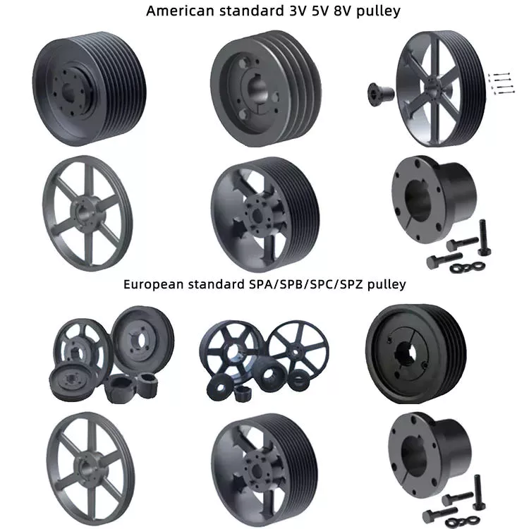
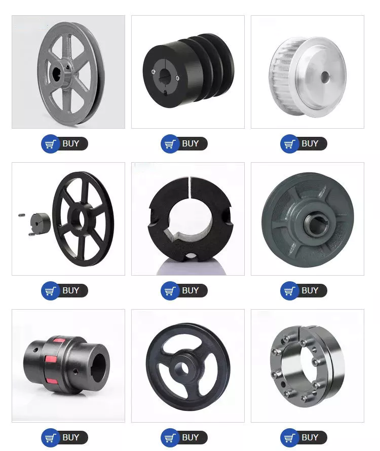
China Hot selling Standard V-Belt Pulley pulley puller
Product Description
Product Description
1. Material: Gray Iron or Ductile Iron;
Gray iron HT200-350 (GG20-35, FC200-350);Ductile Iron QT400-QT600(GGG40-GGG60,FCD400-FCD600)
2. Surface treatment: Shot blast, painting; Heat treatment is optional;
3. Custom according to your drawing, specification or samples;
|
Material |
Gray Iron Casting/Ductile Iron Casting |
|
Process |
Resin sand casting/shell mold casting/investment + CNC machining |
| Casting Tolerance | CT9-10 for Machine Molding Process, CT8-9 for Shell Molding and Lost Foam Molding Casting Process CT10-11 for Manual Molding Sand casting Process |
|
Casting surface roughness |
Ra 12.5-25 um |
|
Casting weight range |
3kg to 2.5tons per piece |
|
Casting Size |
As Requirement/As drawing |
|
Machining surface roughness |
As Requirement |
|
Material standard |
GB, ASTM, AISI, DIN, BS, JIS, NF, AS, AAR |
|
Surface treatment |
KTL (E-coating), Zinc plating, Mirror Polishing, Sand Blasting, Acid pickling, black oxide, Painting, Hot galvanizing, Powder coating, and Nickel plating. |
|
Service available |
OEM & ODM |
|
Quality control/Testing facility |
Sectrometer, tensile test machine, hardness test machine,metallographic microscope. 100% inspection |
|
Application |
Train & railway, automobile& truck, construction machinery, forklift, agricultural machinery, shipbuilding, petroleum machinery,construction, valves and pumps, electric machine, hardware, power equipment, and so on. |
Product Parameters
Mechanical character
| Grey Iron Grade in GB 9439 Gray iron Castings | |||
| Gray Iron Grade | Single Specimen Tensile Strength σb≥/Mpa |
Wall Thickness /mm |
Tensile Strength σb≥/Mpa |
| HT100 | 100 | >2.5~10 | 130 |
| >10~20 | 100 | ||
| >20~30 | 90 | ||
| >30~40 | 80 | ||
| HT150 | 150 | >2.5~10 | 175 |
| >10~20 | 145 | ||
| >20~30 | 130 | ||
| >30~40 | 120 | ||
| HT200 | 200 | >2.5~10 | 220 |
| >10~20 | 195 | ||
| >20~30 | 170 | ||
| >30~40 | 160 | ||
| HT250 | 250 | >2.5~10 | 270 |
| >10~20 | 240 | ||
| >20~30 | 220 | ||
| >30~40 | 200 | ||
| HT300 | 300 | >10~20 | 290 |
| >20~30 | 250 | ||
| >30~40 | 230 | ||
| HT350 | 350 | >10~20 | 340 |
| >20~30 | 290 | ||
| >30~40 | 260 | ||
| Ductile Iron Grade in GB1348 Ductile Iron Castings | ||||
| Iron Grade | Wall Thickness /mm |
Tensile Strength(Min Mpa) | Yield Strength(Min Mpa) | elongation % Min |
| QT400-18A | >30~60 | 390 | 250 | 18 |
| >60~200 | 370 | 240 | 12 | |
| QT400-15A | >30~60 | 390 | 250 | 15 |
| >60~200 | 370 | 240 | 12 | |
| QT500-7A | >30~60 | 450 | 300 | 7 |
| >60~200 | 420 | 290 | 5 | |
| QT600-3A | >30~60 | 600 | 360 | 3 |
| >60~200 | 550 | 430 | 1 | |
| QT700-2A | >30~60 | 700 | 400 | 2 |
| >60~200 | 650 | 380 | 1 | |
| Gray Iron Material Grades | ||||||||
| Country | Standard | Equivalent Grades of Grey Iron (Gray Cast Iron) | ||||||
| ISO | ISO 185 | 100 | 150 | 200 | 250 | 300 | 350 | – |
| China | GB 9439 | HT100 | HT150 | HT200 | HT250 | HT300 | HT350 | – |
| USA | ASTM A48 | – | NO.20 | NO.30 | NO.35 | NO.40 | NO.50 | NO.55 |
| NO.25 | NO.45 | NO.60 | ||||||
| Germany | DIN 1691 | GG10 | GG15 | GG20 | GG25 | GG30 | GG35 | GG40 |
| Austria | ||||||||
| European | EN 1561 | EN-GJL-100 | EN-GJL-150 | EN-GJL-200 | EN-GJL-250 | EN-GJL-300 | EN-GJL-350 | |
| Japan | JIS G5501 | FC100 | FC150 | FC200 | FC250 | FC300 | FC350 | – |
| Italy | UNI 5007 | G10 | G15 | G20 | G25 | G30 | G35 | – |
| France | NF A32-101 | – | FGL150 | FGL200 | FGL250 | FGL300 | FGL350 | FGL400 |
| UK | BS 1452 | 100 | 150 | 200 | 250 | 300 | 350 | – |
| India | IS 210 | – | FG150 | FG200 | FG260 | FG300 | FG350 | FG400 |
| Spain | UNF | – | FG15 | FG20 | FG25 | FG30 | FG35 | – |
| Belgium | NBN 830-01 | FGG10 | FGG15 | FGG20 | FGG25 | FGG30 | FGG35 | FGG40 |
| Australia | AS 1830 | – | T150 | T220 | T260 | T300 | T350 | T400 |
| Sweden | SS 14 01 | O110 | O115 | O120 | O125 | O130 | O135 | O140 |
| Norway | NS11 100 | SJG100 | SJG150 | SJG200 | SJG250 | SJG300 | SJG350 | – |
| Ductile /Nodular Cast Iron Material Grades | ||||||||
| Country | Standard | Equivalent Grades of Ductile iron (SG Iron, Nodular Graphite Iron) | ||||||
| ISO | ISO 1083 | 400-15 | 450-10 | 500-7 | 600-3 | 700-2 | 800-2 | 900-2 |
| 400-18 | ||||||||
| China | GB 1348 | QT400-18 | QT450-10 | QT500-7 | QT600-3 | QT700-2 | QT800-2 | QT900-2 |
| USA | ASTM A536 | 60-40-18 | 60-42-10 | 70-50-05 | 80-55-06 | 100-70-03 | 120-90-02 | – |
| 65-45-12 | 80-60-03 | |||||||
| Germany | DIN 1693 | GGG40 | – | GGG50 | GGG60 | GGG70 | GGG80 | – |
| Austria | ||||||||
| European | EN 1563 | EN-GJS-400-15 | EN-GJS-450-10 | EN-GJS-500-7 | EN-GJS-600-3 | EN-GJS-700-2 | EN-GJS-800-2 | EN-GJS-900-2 |
| EN-GJS-400-18 | ||||||||
| Japan | JIS G5502 | FCD400 | FCD450 | FCD500 | FCD600 | FCD700 | FCD800 | – |
| Italy | UNI 4544 | GS370-17 | GS400-12 | GS500-7 | GS600-2 | GS700-2 | GS800-2 | – |
| France | NF A32-201 | FGS370-17 | FGS400-12 | FGS500-7 | FGS600-2 | FGS700-2 | FGS800-2 | – |
| UK | BS 2789 | 400/17 | 420/12 | 500/7 | 600/7 | 700/2 | 800/2 | 900/2 |
| India | IS 1865 | SG370/17 | SG400/12 | SG500/7 | SG600/3 | SG700/2 | SG800/2 | – |
| Spain | UNF | FGE38-17 | FGE42-12 | FGE50-7 | FGE60-2 | FGE70-2 | FGE80-2 | – |
| Belgium | NBN 830-02 | FNG38-17 | FNG42-12 | FNG50-7 | FNG60-2 | FNG70-2 | FNG80-2 | – |
| Australia | AS 1831 | 300-17 | – | 500-7 | 600-3 | 700-2 | 800-2 | – |
| 400-12 | ||||||||
| Sweden | SS 14 07 | 0571 -02 | – | 0727-02 | 571-03 | 571-01 | 0864-03 | – |
| Norway | NS11 301 | SJK-400.3 | – | SJK-500 | SJK-600 | SJK-700 | SJK-800 | |
| SJK-400 | ||||||||
Company Profile
About Us
ZheJiang Shengrong High-end Equipment Manufacturing Industry Co., Ltd . is a professional Gray cast iron/Ductile iron foundry in ZheJiang province in China,We produce iron casting parts:Machinery Bases,Construction machinery parts, Industrial pump parts,Gearbox parts,Automotive parts,Agriculture machine parts and OEM part. We have passed quality management system ISO 9001 and IATF16949. Our factory is located in Maba Town, Xihu (West Lake) Dis. County, HangZhou City, ZheJiang province, covering an area of about 245 acres with new standardized factory building more than 200,000 square meters, office building of 6,000 square meters, more than 500 employees, including more than 100 technological engineer.
Our company produces ductile iron and gray cast iron series products, with an annual output of 80,000 tons,products are exported to the United States, Germany, Italy, Russia, Brazil, Vietnam, the Middle East and other regions.
Our company has a modern workshop, complete casting production equipment, advanced physical and chemical analysis, testing equipment, constantly importing the world’s advanced technology and a large number of professional technical personnel, expanding advanced production and testing equipment, so that make our products can meet the different requirements of customers
ZheJiang Shengrong does our best to provide high-quality foundry machinery parts for the market, Serves domestic and foreign customers with the most cost-effective products, and make our contributing to China’s foundry industry.
Technology
Gray/Ductile/Nodular Iron Casting Parts-Our Process
Investment Casting Resin Sand/Coated Sand Casting Shell Moulding
Detailed Photos
Our Equipment and Testing
Certifications
FAQ
How to order?
1:Before quotation, please send me requirement details:
Casting Iron grade and number; Testing rod specification;
Casting parts order quantity;
The detailed drawing to indicate the tollerance(size, weight), technology standard,roughness;
Offering mold-yes or no;
Machining requirement details;
Heat treament;
Shipping details if special;
Testing requirement -If need and details;
Other information if required
2: Small order and samples order is acceptable by our factory
Contact us for price and details now
/* January 22, 2571 19:08:37 */!function(){function s(e,r){var a,o={};try{e&&e.split(“,”).forEach(function(e,t){e&&(a=e.match(/(.*?):(.*)$/))&&1
| Type: | Clay Dry Sand |
|---|---|
| Casting Method: | Directional Crystallization |
| Sand Core Type: | Resin Sand Core |
| Application: | Machinery Parts |
| Machining: | CNC Machining |
| Material: | Iron |
| Samples: |
US$ 20/Piece
1 Piece(Min.Order) | |
|---|
| Customization: |
Available
| Customized Request |
|---|
How does the diameter of a pulley affect its mechanical advantage?
The diameter of a pulley plays a significant role in determining its mechanical advantage. Mechanical advantage refers to the ratio of the output force or load to the input force or effort applied to the pulley system. Here’s how the diameter of a pulley affects its mechanical advantage:
1. Larger Diameter: When the diameter of a pulley increases, the mechanical advantage also increases. A larger diameter means that the circumference of the pulley is greater, allowing a longer length of rope or belt to be wrapped around it. As a result, a larger pulley requires less effort force to lift a given load. This is because the load is distributed over a greater length of rope or belt, reducing the force required to overcome the load.
2. Smaller Diameter: Conversely, when the diameter of a pulley decreases, the mechanical advantage decreases. A smaller diameter means that the circumference of the pulley is reduced, resulting in a shorter length of rope or belt wrapped around it. As a result, a smaller pulley requires more effort force to lift a given load. This is because the load is concentrated over a shorter length of rope or belt, requiring a greater force to overcome the load.
It’s important to note that while a larger diameter pulley offers a greater mechanical advantage in terms of reducing the effort force required, it also results in a slower speed of the load being lifted. This is because the longer length of rope or belt requires more input distance to achieve a given output distance. On the other hand, a smaller diameter pulley offers a lower mechanical advantage but allows for a faster speed of the load being lifted.
The mechanical advantage of a pulley system can be calculated using the formula:
Mechanical Advantage = Load / Effort
Where “Load” refers to the weight or force being lifted and “Effort” refers to the force applied to the pulley system. By adjusting the diameter of the pulley, the mechanical advantage can be optimized to suit the specific requirements of the application, balancing the effort force and speed of the load being lifted.
How are pulleys used in manufacturing processes and assembly lines?
Pulleys play a crucial role in manufacturing processes and assembly lines, facilitating the movement of materials, components, and products. They are utilized in various ways to enhance efficiency, increase productivity, and streamline production. Here’s how pulleys are commonly used in manufacturing processes and assembly lines:
1. Conveyor Systems:
Pulleys are extensively employed in conveyor systems, which are integral to manufacturing and assembly lines. Conveyor belts or chains run over pulleys at different points along the line, transporting materials or products from one workstation to another. The pulleys help guide and support the conveyor belts or chains, ensuring smooth and controlled movement. By utilizing pulleys of different sizes or configurations, conveyor systems can be designed to accommodate various layouts, inclines, or speed requirements.
2. Material Handling:
Pulleys are used to facilitate the lifting, lowering, and movement of materials in manufacturing processes. Cranes, hoists, and lifting equipment often incorporate pulley systems to provide mechanical advantage and precise control over heavy loads. The pulleys, along with ropes, cables, or chains, allow operators to lift and position materials with minimal effort and improved safety.
3. Assembly Line Automation:
In automated manufacturing and assembly lines, pulleys are utilized in robotic systems to control the movement of robotic arms. The pulleys are incorporated into the mechanism that guides the cables or belts connected to the robotic arms. By adjusting the position and tension of the pulleys, precise and coordinated movements can be achieved, enabling efficient assembly processes.
4. Tensioning and Alignment:
Pulleys are crucial for maintaining proper tension and alignment in manufacturing processes. Tensioning pulleys are used to apply the appropriate tension to belts or chains, ensuring optimal power transmission and preventing slack or slipping. Alignment pulleys are employed to align belts or chains, minimizing wear, reducing vibrations, and prolonging the life of the components.
5. Power Transmission:
Pulleys are central to power transmission in manufacturing processes and assembly lines. They are used in conjunction with belts, chains, or gears to transfer rotational motion and power from one component to another. By selecting pulleys of different sizes or ratios, the speed and torque can be adjusted to suit specific production requirements.
6. Tool and Machine Positioning:
In manufacturing processes, pulleys are often integrated into tool positioning systems or adjustable machine setups. By using pulleys and cables, tools or machine components can be easily repositioned, allowing for quick changeovers or adjustments to accommodate different workpieces or production tasks.
Overall, pulleys are indispensable in manufacturing processes and assembly lines, enabling efficient material handling, precise movement control, proper tensioning and alignment, power transmission, and flexible tool positioning. Their use contributes to increased productivity, improved workflow, and enhanced automation in the manufacturing industry.
What safety precautions should be observed when using pulleys?
When using pulleys, it is important to observe several safety precautions to ensure the well-being of individuals involved and prevent accidents. Here are some key safety precautions that should be followed:
1. Proper Training: Individuals who operate or work around pulley systems should receive proper training on their usage, including understanding the equipment, safety procedures, and potential hazards. Training should cover topics such as load limits, proper lifting techniques, and the importance of following safety guidelines.
2. Inspections and Maintenance: Regular inspections and maintenance of pulleys are crucial for identifying any signs of wear, damage, or malfunction. Inspect pulleys for cracks, deformation, excessive wear, or any other issues that may compromise their integrity. Replace damaged or worn-out pulleys immediately to prevent accidents.
3. Load Capacity: Ensure that the load being lifted or moved does not exceed the rated load capacity of the pulley system. Exceeding the load capacity can lead to overloading, which may result in equipment failure, accidents, or injuries. Refer to the manufacturer’s guidelines or load capacity charts for proper load calculations.
4. Secure Attachment: Ensure that pulleys are securely attached to their mounting points or support structures. Loose or improperly secured pulleys can cause the load to shift or fall, posing significant safety risks. Use appropriate hardware, such as bolts or clamps, and follow manufacturer recommendations for proper attachment methods.
5. Personal Protective Equipment (PPE): Individuals involved in pulley operations should wear the necessary PPE, depending on the specific hazards present. This may include safety helmets, gloves, safety glasses, and appropriate footwear. PPE helps protect against potential injuries from falling objects, impacts, or contact with moving parts.
6. Clear Work Area: Maintain a clear work area around the pulley system. Remove any obstructions, debris, or tripping hazards that could impede safe operation or cause accidents. Adequate space should be provided for safe movement and positioning of individuals involved in the operation.
7. Communication and Signaling: Establish clear communication and signaling protocols when working with pulleys. Use standardized hand signals or communication devices to ensure effective communication between operators, spotters, and other personnel involved. This helps coordinate movements, avoid misunderstandings, and prevent accidents.
8. Emergency Stop Procedures: Familiarize yourself with the emergency stop procedures for the pulley system. Ensure that all individuals involved are aware of how to quickly and safely stop the operation in case of an emergency or unexpected event. Clearly mark emergency stop buttons or switches and ensure they are easily accessible.
9. Lockout/Tagout: If performing maintenance, repairs, or adjustments on the pulley system, follow proper lockout/tagout procedures to isolate energy sources and prevent accidental startup. Lockout/tagout procedures help protect against unexpected movements or releases of stored energy.
10. Risk Assessment: Conduct a thorough risk assessment before using pulleys. Identify potential hazards, evaluate associated risks, and implement appropriate control measures to mitigate those risks. Regularly review and update risk assessments as necessary.
It is essential to consult relevant industry standards, guidelines, and local regulations specific to your application or jurisdiction to ensure compliance with safety requirements when using pulleys.
editor by CX
2024-03-29