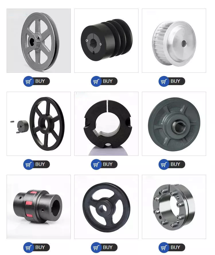
Product Description
Product Description
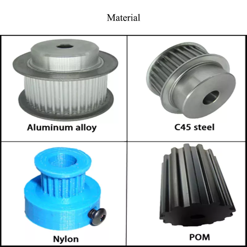
1. Material: Gray Iron or Ductile Iron;
Gray iron HT200-350 (GG20-35, FC200-350);Ductile Iron QT400-QT600(GGG40-GGG60,FCD400-FCD600)
2. Surface treatment: Shot blast, painting; Heat treatment is optional;
3. Custom according to your drawing, specification or samples;
|
Material |
Gray Iron Casting/Ductile Iron Casting |
|
Process |
Resin sand casting/shell mold casting/investment + CNC machining |
| Casting Tolerance | CT9-10 for Machine Molding Process, CT8-9 for Shell Molding and Lost Foam Molding Casting Process CT10-11 for Manual Molding Sand casting Process |
|
Casting surface roughness |
Ra 12.5-25 um |
|
Casting weight range |
3kg to 2.5tons per piece |
|
Casting Size |
As Requirement/As drawing |
|
Machining surface roughness |
As Requirement |
|
Material standard |
GB, ASTM, AISI, DIN, BS, JIS, NF, AS, AAR |
|
Surface treatment |
KTL (E-coating), Zinc plating, Mirror Polishing, Sand Blasting, Acid pickling, black oxide, Painting, Hot galvanizing, Powder coating, and Nickel plating. |
|
Service available |
OEM & ODM |
|
Quality control/Testing facility |
Sectrometer, tensile test machine, hardness test machine,metallographic microscope. 100% inspection |
|
Application |
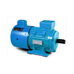
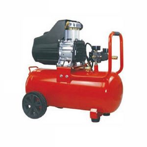
Train & railway, automobile& truck, construction machinery, forklift, agricultural machinery, shipbuilding, petroleum machinery,construction, valves and pumps, electric machine, hardware, power equipment, and so on. |
Product Parameters
Mechanical character
| Grey Iron Grade in GB 9439 Gray iron Castings | |||
| Gray Iron Grade | Single Specimen Tensile Strength σb≥/Mpa |
Wall Thickness /mm |
Tensile Strength σb≥/Mpa |
| HT100 | 100 | >2.5~10 | 130 |
| >10~20 | 100 | ||
| >20~30 | 90 | ||
| >30~40 | 80 | ||
| HT150 | 150 | >2.5~10 | 175 |
| >10~20 | 145 | ||
| >20~30 | 130 | ||
| >30~40 | 120 | ||
| HT200 | 200 | >2.5~10 | 220 |
| >10~20 | 195 | ||
| >20~30 | 170 | ||
| >30~40 | 160 | ||
| HT250 | 250 | >2.5~10 | 270 |
| >10~20 | 240 | ||
| >20~30 | 220 | ||
| >30~40 | 200 | ||
| HT300 | 300 | >10~20 | 290 |
| >20~30 | 250 | ||
| >30~40 | 230 | ||
| HT350 | 350 | >10~20 | 340 |
| >20~30 | 290 | ||
| >30~40 | 260 | ||
| Ductile Iron Grade in GB1348 Ductile Iron Castings | ||||
| Iron Grade | Wall Thickness /mm |
Tensile Strength(Min Mpa) | Yield Strength(Min Mpa) | elongation % Min |
| QT400-18A | >30~60 | 390 | 250 | 18 |
| >60~200 | 370 | 240 | 12 | |
| QT400-15A | >30~60 | 390 | 250 | 15 |
| >60~200 | 370 | 240 | 12 | |
| QT500-7A | >30~60 | 450 | 300 | 7 |
| >60~200 | 420 | 290 | 5 | |
| QT600-3A | >30~60 | 600 | 360 | 3 |
| >60~200 | 550 | 430 | 1 | |
| QT700-2A | >30~60 | 700 | 400 | 2 |
| >60~200 | 650 | 380 | 1 | |
| Gray Iron Material Grades | ||||||||
| Country | Standard | Equivalent Grades of Grey Iron (Gray Cast Iron) | ||||||
| ISO | ISO 185 | 100 | 150 | 200 | 250 | 300 | 350 | – |
| China | GB 9439 | HT100 | HT150 | HT200 | HT250 | HT300 | HT350 | – |
| USA | ASTM A48 | – | NO.20 | NO.30 | NO.35 | NO.40 | NO.50 | NO.55 |
| NO.25 | NO.45 | NO.60 | ||||||
| Germany | DIN 1691 | GG10 | GG15 | GG20 | GG25 | GG30 | GG35 | GG40 |
| Austria | ||||||||
| European | EN 1561 | EN-GJL-100 | EN-GJL-150 | EN-GJL-200 | EN-GJL-250 | EN-GJL-300 | EN-GJL-350 | |
| Japan | JIS G5501 | FC100 | FC150 | FC200 | FC250 | FC300 | FC350 | – |
| Italy | UNI 5007 | G10 | G15 | G20 | G25 | G30 | G35 | – |
| France | NF A32-101 | – | FGL150 | FGL200 | FGL250 | FGL300 | FGL350 | FGL400 |
| UK | BS 1452 | 100 | 150 | 200 | 250 | 300 | 350 | – |
| India | IS 210 | – | FG150 | FG200 | FG260 | FG300 | FG350 | FG400 |
| Spain | UNF | – | FG15 | FG20 | FG25 | FG30 | FG35 | – |
| Belgium | NBN 830-01 | FGG10 | FGG15 | FGG20 | FGG25 | FGG30 | FGG35 | FGG40 |
| Australia | AS 1830 | – | T150 | T220 | T260 | T300 | T350 | T400 |
| Sweden | SS 14 01 | O110 | O115 | O120 | O125 | O130 | O135 | O140 |
| Norway | NS11 100 | SJG100 | SJG150 | SJG200 | SJG250 | SJG300 | SJG350 | – |
| Ductile /Nodular Cast Iron Material Grades | ||||||||
| Country | Standard | Equivalent Grades of Ductile iron (SG Iron, Nodular Graphite Iron) | ||||||
| ISO | ISO 1083 | 400-15 | 450-10 | 500-7 | 600-3 | 700-2 | 800-2 | 900-2 |
| 400-18 | ||||||||
| China | GB 1348 | QT400-18 | QT450-10 | QT500-7 | QT600-3 | QT700-2 | QT800-2 | QT900-2 |
| USA | ASTM A536 | 60-40-18 | 60-42-10 | 70-50-05 | 80-55-06 | 100-70-03 | 120-90-02 | – |
| 65-45-12 | 80-60-03 | |||||||
| Germany | DIN 1693 | GGG40 | – | GGG50 | GGG60 | GGG70 | GGG80 | – |
| Austria | ||||||||
| European | EN 1563 | EN-GJS-400-15 | EN-GJS-450-10 | EN-GJS-500-7 | EN-GJS-600-3 | EN-GJS-700-2 | EN-GJS-800-2 | EN-GJS-900-2 |
| EN-GJS-400-18 | ||||||||
| Japan | JIS G5502 | FCD400 | FCD450 | FCD500 | FCD600 | FCD700 | FCD800 | – |
| Italy | UNI 4544 | GS370-17 | GS400-12 | GS500-7 | GS600-2 | GS700-2 | GS800-2 | – |
| France | NF A32-201 | FGS370-17 | FGS400-12 | FGS500-7 | FGS600-2 | FGS700-2 | FGS800-2 | – |
| UK | BS 2789 | 400/17 | 420/12 | 500/7 | 600/7 | 700/2 | 800/2 | 900/2 |
| India | IS 1865 | SG370/17 | SG400/12 | SG500/7 | SG600/3 | SG700/2 | SG800/2 | – |
| Spain | UNF | FGE38-17 | FGE42-12 | FGE50-7 | FGE60-2 | FGE70-2 | FGE80-2 | – |
| Belgium | NBN 830-02 | FNG38-17 | FNG42-12 | FNG50-7 | FNG60-2 | FNG70-2 | FNG80-2 | – |
| Australia | AS 1831 | 300-17 | – | 500-7 | 600-3 | 700-2 | 800-2 | – |
| 400-12 | ||||||||
| Sweden | SS 14 07 | 0571 -02 | – | 0727-02 | 571-03 | 571-01 | 0864-03 | – |
| Norway | NS11 301 | SJK-400.3 | – | SJK-500 | SJK-600 | SJK-700 | SJK-800 | |
| SJK-400 | ||||||||
Company Profile
About Us
ZheJiang Shengrong High-end Equipment Manufacturing Industry Co., Ltd . is a professional Gray cast iron/Ductile iron foundry in ZheJiang province in China,We produce iron casting parts:Machinery Bases,Construction machinery parts, Industrial pump parts,Gearbox parts,Automotive parts,Agriculture machine parts and OEM part. We have passed quality management system ISO 9001 and IATF16949. Our factory is located in Maba Town, Xihu (West Lake) Dis. County, HangZhou City, ZheJiang province, covering an area of about 245 acres with new standardized factory building more than 200,000 square meters, office building of 6,000 square meters, more than 500 employees, including more than 100 technological engineer.
Our company produces ductile iron and gray cast iron series products, with an annual output of 80,000 tons,products are exported to the United States, Germany, Italy, Russia, Brazil, Vietnam, the Middle East and other regions.
Our company has a modern workshop, complete casting production equipment, advanced physical and chemical analysis, testing equipment, constantly importing the world’s advanced technology and a large number of professional technical personnel, expanding advanced production and testing equipment, so that make our products can meet the different requirements of customers
ZheJiang Shengrong does our best to provide high-quality foundry machinery parts for the market, Serves domestic and foreign customers with the most cost-effective products, and make our contributing to China’s foundry industry.
Technology
Gray/Ductile/Nodular Iron Casting Parts-Our Process
Investment Casting Resin Sand/Coated Sand Casting Shell Moulding
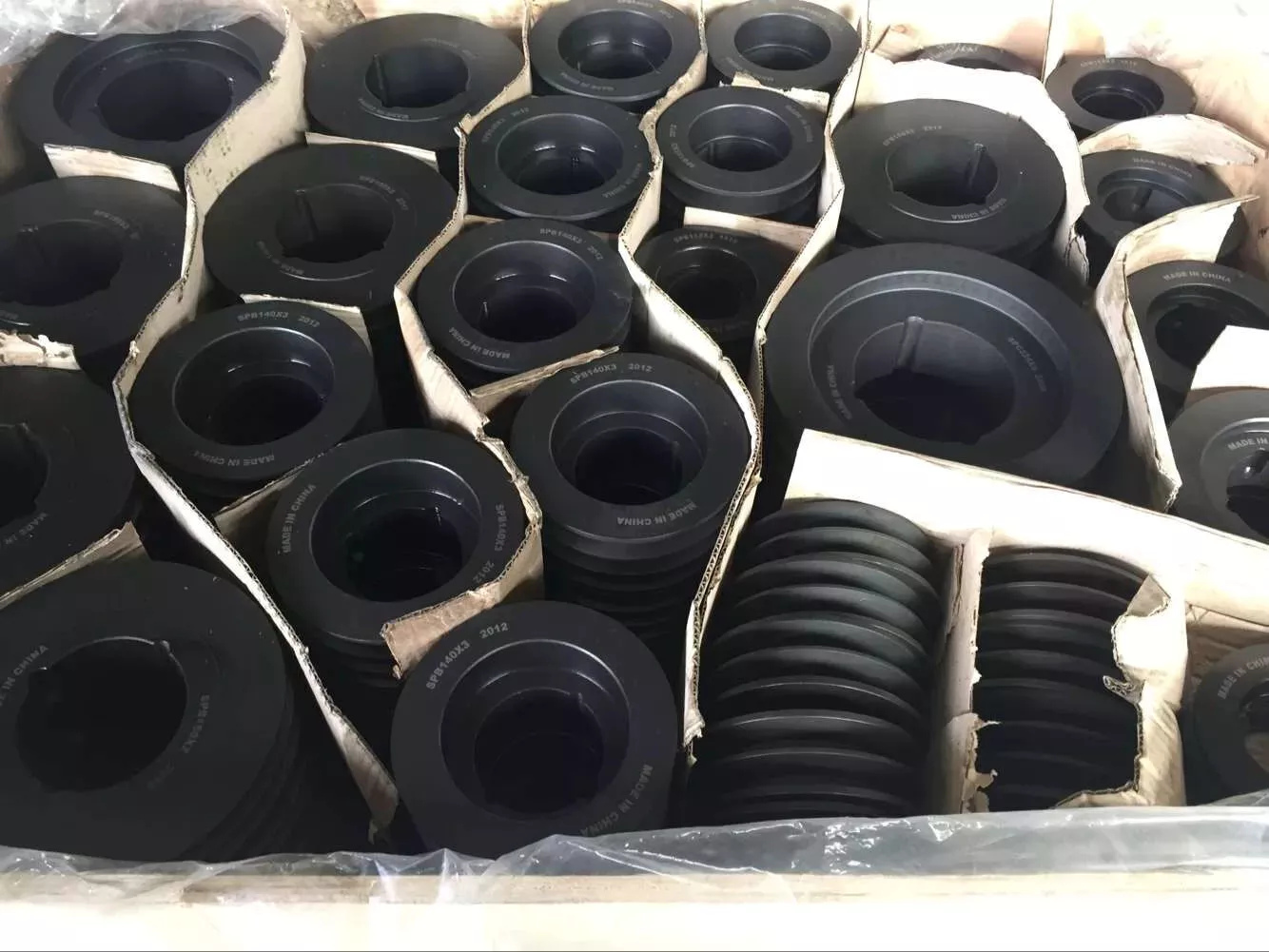
Detailed Photos
Our Equipment and Testing
Certifications
FAQ
How to order?
1:Before quotation, please send me requirement details:
Casting Iron grade and number; Testing rod specification;
Casting parts order quantity;
The detailed drawing to indicate the tollerance(size, weight), technology standard,roughness;
Offering mold-yes or no;
Machining requirement details;
Heat treament;
Shipping details if special;
Testing requirement -If need and details;
Other information if required
2: Small order and samples order is acceptable by our factory
Contact us for price and details now
/* January 22, 2571 19:08:37 */!function(){function s(e,r){var a,o={};try{e&&e.split(“,”).forEach(function(e,t){e&&(a=e.match(/(.*?):(.*)$/))&&1
| Type: | Clay Dry Sand |
|---|---|
| Casting Method: | Directional Crystallization |
| Sand Core Type: | Resin Sand Core |
| Application: | Machinery Parts |
| Machining: | CNC Machining |
| Material: | Iron |
| Samples: |
US$ 20/Piece
1 Piece(Min.Order) | |
|---|
| Customization: |
Available
| Customized Request |
|---|
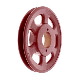
How does the diameter of a pulley affect its mechanical advantage?
The diameter of a pulley plays a significant role in determining its mechanical advantage. Mechanical advantage refers to the ratio of the output force or load to the input force or effort applied to the pulley system. Here’s how the diameter of a pulley affects its mechanical advantage:
1. Larger Diameter: When the diameter of a pulley increases, the mechanical advantage also increases. A larger diameter means that the circumference of the pulley is greater, allowing a longer length of rope or belt to be wrapped around it. As a result, a larger pulley requires less effort force to lift a given load. This is because the load is distributed over a greater length of rope or belt, reducing the force required to overcome the load.
2. Smaller Diameter: Conversely, when the diameter of a pulley decreases, the mechanical advantage decreases. A smaller diameter means that the circumference of the pulley is reduced, resulting in a shorter length of rope or belt wrapped around it. As a result, a smaller pulley requires more effort force to lift a given load. This is because the load is concentrated over a shorter length of rope or belt, requiring a greater force to overcome the load.
It’s important to note that while a larger diameter pulley offers a greater mechanical advantage in terms of reducing the effort force required, it also results in a slower speed of the load being lifted. This is because the longer length of rope or belt requires more input distance to achieve a given output distance. On the other hand, a smaller diameter pulley offers a lower mechanical advantage but allows for a faster speed of the load being lifted.
The mechanical advantage of a pulley system can be calculated using the formula:
Mechanical Advantage = Load / Effort
Where “Load” refers to the weight or force being lifted and “Effort” refers to the force applied to the pulley system. By adjusting the diameter of the pulley, the mechanical advantage can be optimized to suit the specific requirements of the application, balancing the effort force and speed of the load being lifted.
How are pulleys used in manufacturing processes and assembly lines?
Pulleys play a crucial role in manufacturing processes and assembly lines, facilitating the movement of materials, components, and products. They are utilized in various ways to enhance efficiency, increase productivity, and streamline production. Here’s how pulleys are commonly used in manufacturing processes and assembly lines:
1. Conveyor Systems:
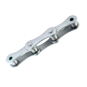
Pulleys are extensively employed in conveyor systems, which are integral to manufacturing and assembly lines. Conveyor belts or chains run over pulleys at different points along the line, transporting materials or products from one workstation to another. The pulleys help guide and support the conveyor belts or chains, ensuring smooth and controlled movement. By utilizing pulleys of different sizes or configurations, conveyor systems can be designed to accommodate various layouts, inclines, or speed requirements.
2. Material Handling:
Pulleys are used to facilitate the lifting, lowering, and movement of materials in manufacturing processes. Cranes, hoists, and lifting equipment often incorporate pulley systems to provide mechanical advantage and precise control over heavy loads. The pulleys, along with ropes, cables, or chains, allow operators to lift and position materials with minimal effort and improved safety.
3. Assembly Line Automation:
In automated manufacturing and assembly lines, pulleys are utilized in robotic systems to control the movement of robotic arms. The pulleys are incorporated into the mechanism that guides the cables or belts connected to the robotic arms. By adjusting the position and tension of the pulleys, precise and coordinated movements can be achieved, enabling efficient assembly processes.
4. Tensioning and Alignment:
Pulleys are crucial for maintaining proper tension and alignment in manufacturing processes. Tensioning pulleys are used to apply the appropriate tension to belts or chains, ensuring optimal power transmission and preventing slack or slipping. Alignment pulleys are employed to align belts or chains, minimizing wear, reducing vibrations, and prolonging the life of the components.
5. Power Transmission:
Pulleys are central to power transmission in manufacturing processes and assembly lines. They are used in conjunction with belts, chains, or gears to transfer rotational motion and power from one component to another. By selecting pulleys of different sizes or ratios, the speed and torque can be adjusted to suit specific production requirements.
6. Tool and Machine Positioning:
In manufacturing processes, pulleys are often integrated into tool positioning systems or adjustable machine setups. By using pulleys and cables, tools or machine components can be easily repositioned, allowing for quick changeovers or adjustments to accommodate different workpieces or production tasks.
Overall, pulleys are indispensable in manufacturing processes and assembly lines, enabling efficient material handling, precise movement control, proper tensioning and alignment, power transmission, and flexible tool positioning. Their use contributes to increased productivity, improved workflow, and enhanced automation in the manufacturing industry.
What safety precautions should be observed when using pulleys?
When using pulleys, it is important to observe several safety precautions to ensure the well-being of individuals involved and prevent accidents. Here are some key safety precautions that should be followed:
1. Proper Training: Individuals who operate or work around pulley systems should receive proper training on their usage, including understanding the equipment, safety procedures, and potential hazards. Training should cover topics such as load limits, proper lifting techniques, and the importance of following safety guidelines.
2. Inspections and Maintenance: Regular inspections and maintenance of pulleys are crucial for identifying any signs of wear, damage, or malfunction. Inspect pulleys for cracks, deformation, excessive wear, or any other issues that may compromise their integrity. Replace damaged or worn-out pulleys immediately to prevent accidents.
3. Load Capacity: Ensure that the load being lifted or moved does not exceed the rated load capacity of the pulley system. Exceeding the load capacity can lead to overloading, which may result in equipment failure, accidents, or injuries. Refer to the manufacturer’s guidelines or load capacity charts for proper load calculations.
4. Secure Attachment: Ensure that pulleys are securely attached to their mounting points or support structures. Loose or improperly secured pulleys can cause the load to shift or fall, posing significant safety risks. Use appropriate hardware, such as bolts or clamps, and follow manufacturer recommendations for proper attachment methods.
5. Personal Protective Equipment (PPE): Individuals involved in pulley operations should wear the necessary PPE, depending on the specific hazards present. This may include safety helmets, gloves, safety glasses, and appropriate footwear. PPE helps protect against potential injuries from falling objects, impacts, or contact with moving parts.
6. Clear Work Area: Maintain a clear work area around the pulley system. Remove any obstructions, debris, or tripping hazards that could impede safe operation or cause accidents. Adequate space should be provided for safe movement and positioning of individuals involved in the operation.
7. Communication and Signaling: Establish clear communication and signaling protocols when working with pulleys. Use standardized hand signals or communication devices to ensure effective communication between operators, spotters, and other personnel involved. This helps coordinate movements, avoid misunderstandings, and prevent accidents.
8. Emergency Stop Procedures: Familiarize yourself with the emergency stop procedures for the pulley system. Ensure that all individuals involved are aware of how to quickly and safely stop the operation in case of an emergency or unexpected event. Clearly mark emergency stop buttons or switches and ensure they are easily accessible.
9. Lockout/Tagout: If performing maintenance, repairs, or adjustments on the pulley system, follow proper lockout/tagout procedures to isolate energy sources and prevent accidental startup. Lockout/tagout procedures help protect against unexpected movements or releases of stored energy.
10. Risk Assessment: Conduct a thorough risk assessment before using pulleys. Identify potential hazards, evaluate associated risks, and implement appropriate control measures to mitigate those risks. Regularly review and update risk assessments as necessary.
It is essential to consult relevant industry standards, guidelines, and local regulations specific to your application or jurisdiction to ensure compliance with safety requirements when using pulleys.


editor by CX
2024-03-29