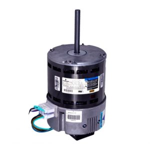
Hall Pace Encoder Motor
Encoder board specification
1. Board measurement: 26*22*1.2mm
2. Terminal pin definition:
G: hall energy unfavorable
H1: hall H1 output signal, square wave
H2: hall H2 output sign, square wave
V: corridor electricity positive
M+: motor good pole
M-: motor negative pole
Remark:
1. The voltage between V-G is established according to the electricity supply voltage of the single chip microcomputer employed, normally three.3V or 5V is utilized.
2. The frequency of the output square wave of H1 and H2 and the speed of the motor are connected to the number of poles of the utilised magnetic disk.
three. The voltage among M+ and M- is set according to the motor voltage used.
three. Principle
three.1 Motor velocity measurement: The Hall sensor can sense the N and S poles of the magnetic plate. We use the Corridor of the S pole to feeling that when each and every Hall sensor senses the S of the magnetic plate, the Corridor output will output a high level When the N pole of the magnetic plate, the Hall output will output a low stage. When the motor rotates repeatedly, a sq. wave is output at the Corridor output. The pace of the motor can be identified primarily based on the period of time T of the output sq. wave. Assuming that the magnetic disk we use is the P-polarity, the calculated sq.-wave time period is T. Measure motor pace: n=sixty/PT.
three.2 Motor reversal measurement: Two Corridor sensors are put in two different positions in the circuit. When the motor turns differently, the two Corridor outputs have different sq. waves.
When the motor rotates forward, H1 detects the rising edge, H2 enters the slipping edge when the motor reverses, H1 detects the slipping edge, H2 is also the slipping edge.