Product Description
Conveyor Pulley is manufactured as per customer requirement,with main design under national standard,quality inspection focusing on shaft core,welded joint,rubber material and hardness,dynamic balance and so on for longer product life time.
| Drive/Head Pulley – A conveyor pulley used for the purpose of driving a conveyor belt. Typically mounted in external bearings and driven by an external drive source. |
| Return/Tail Pulley – A conveyor pulley used for the purpose of redirecting a conveyor belt back to the drive pulley. Tail pulleys can utilize internal bearings or can be mounted in external bearings and are typically located at the end of the conveyor bed. Tail pulleys commonly serve the purpose of a Take-Up pulley on conveyors of shorter lengths. |
| Snub Pulley – A conveyor pulley used to increase belt wrap around a drive pulley, typically for the purpose of improving traction. |
| Take-Up Pulley – A conveyor pulley used to remove slack and provide tension to a conveyor belt. Take-Up pulleys are more common to conveyors of longer lengths. |
| Bend Pulley – A conveyor pulley used to redirect the belt and provide belt tension where bends occur in the conveyor system. |
The specification of pulley:
Drive Drum: is the main component of power transmission. The drum can be divided into single drum (the angle of the belt to the drum is 210 ° ~ 230 °) , Double Drum (the angle of the belt to the drum is up to 350 °) and
multi-drum (used for high power) .
Bend Drum: is used for changing the running direction of the conveyor belt or increasing the surrounding angle of the conveyor belt on the driving roller, and the roller adopts a smooth rubber surface . The drum shaft shall be forgings and shall be nondestructive tested and the inspection report shall be provided.
The Various Surface of Pulley:
Conveyor pulley lagging is essential to improve conveyor belt performance, the combination of our pulley lagging can reduces belt slippage, improve tracking and extends life of belt, bearing & other components.
| PLAIN LAGGING:This style of finish is suitable for any pulley in the conveyor system where watershed is not necessary. It provides additional protection against belt wear, therefore, increasing the life of the pulley. |
| DIAMOND GROOVE LAGGING:This is the standard pattern on all Specdrum lagged conveyor pulleys. It is primarily used for reversing conveyor drive pulleys. It is also often used to allow bi-directional pulley rotation, and the pattern allows water to be dispersed away from the belt. |
| HERRINGBONE LAGGING:The herringbone pattern’s grooves are in the direction of rotation, and offers superior tractive properties. Each groove allows water and other liquids to escape between the face of the drum pulley and the belt. Herringbone grooved pulleys are directional and should be applied to the conveyor in a manner in which the grooves point toward the direction of the belt travel. |
| CHEVRON LAGGING:Some customers specify that the points of the groove should meet – as done in Chevron styled lagging. As before with the herringbone style, this would be used on drive drum pulleys and should be fitted in the correct manner, so as to allow proper use of the pattern and water dispersion also. |
| CERAMIC LAGGING:The Ceramic tiles are moulded into the lagging which is then cold bonded to the drum pulley. This style of finish allows excellent traction and reduces slippage, meaning that the belt tension is lower and, therefore as a result, increases the life of the pulley. |
| WELD-ON STRIP LAGGING: Weld-On Strip Lagging can be applied to bi-directional pulleys, and also has a finish to allow the easy dispersion of water or any fluids between the drum pulley and the belt. |
The Components of Pulley:
| 1. Drum or Shell:The drum is the portion of the pulley in direct contact with the belt. The shell is fabricated from either a rolled sheet of steel or from hollow steel tubing. |
| 2.Diaphragm Plates: The diaphragm or end plates of a pulley are circular discs which are fabricated from thick steel plate and which are welded into the shell at each end, to strengthen the drum.The end plates are bored in their centre to accommodate the pulley Shaft and the hubs for the pulley locking elements. |
| 3.Shaft :The shaft is designed to accommodate all the applied forces from the belt and / or the drive unit, with minimum deflection. The shaft is located and locked to the hubs of the end discs by means of a locking elements. The shaft and hence pulley shafts are often stepped. |
| 4.Locking Elements:These are high-precision manufactured items which are fitted over the shaft and into the pulley hubs. The locking elements attach the pulley firmly to the shaft via the end plates. |
| 5.Hubs:The hubs are fabricated and machined housings which are welded into the end plates. |
| 6.Lagging: It is sometimes necessary or desirable to improve the friction between the conveyor belt and the pulley in order to improve the torque that can be transmitted through a drive pulley. Improved traction over a pulley also assists with the training of the belt. In such cases pulley drum surfaces are `lagged` or covered in a rubberized material. |
| 7.Bearing: Bearings used for conveyor pulleys are generally spherical roller bearings, chosen for their radial and axial load supporting characteristics. The bearings are self-aligning relative to their raceways, which means that the bearings can be ‘misaligned’ relative to the shaft and plummer blocks, to a certain degree. In practical terms this implies that the bending of the shaft under loaded conditions as well as minor misalignment of the pulley support structure, can be accommodated by the bearing. |
The Production Process of Pulley:
Our Products:
| 1.Different types of Laggings can meet all kinds of complex engineering requirements. |
| 2.Advanced welding technology ensures the connection strength between Shell and End-Disk. |
| 3.High-strength Locking Elements can satisfy torque and bending requirements. |
| 4.T-shape End-Discs provide highest performance and reliability. |
| 5.The standardized Bearing Assembly makes it more convenient for the end user to replace it. |
| 6.Excellent raw material and advanced processing technology enable the shaft can withstand enough torque. |
| 7.Low maintenance for continued operation and low total cost of ownership. |
| 8.Scientific design process incorporating Finite Element Analysis. |
Our Workshop:
/* January 22, 2571 19:08:37 */!function(){function s(e,r){var a,o={};try{e&&e.split(“,”).forEach(function(e,t){e&&(a=e.match(/(.*?):(.*)$/))&&1
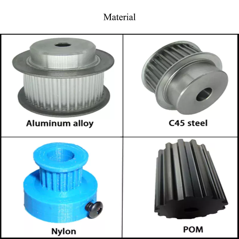
| Material: | Carbon Steel |
|---|---|
| Surface Treatment: | Baking Paint |
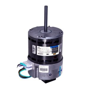
| Motor Type: | Frequency Control Motor |
| Samples: |
US$ 40/Piece
1 Piece(Min.Order) | Order Sample Free sample
|
|---|
| Customization: |
Available
| Customized Request |
|---|
.shipping-cost-tm .tm-status-off{background: none;padding:0;color: #1470cc}
|
Shipping Cost:
Estimated freight per unit. |
about shipping cost and estimated delivery time. |
|---|
| Payment Method: |
|
|---|---|
|
Initial Payment Full Payment |
| Currency: | US$ |
|---|
| Return&refunds: | You can apply for a refund up to 30 days after receipt of the products. |
|---|
How do multiple pulleys in a block and tackle system work together?
In a block and tackle system, multiple pulleys are used in combination to create a mechanical advantage, allowing for easier lifting of heavy loads. The pulleys in a block and tackle system work together in the following manner:
1. Load Distribution: The weight of the load to be lifted is distributed over multiple strands of rope or cable that pass through the pulleys. This distribution of weight helps in reducing the force required to lift the load.
2. Mechanical Advantage: The mechanical advantage in a block and tackle system is achieved by increasing the number of rope segments that support the load. Each additional pulley increases the number of rope segments, which in turn reduces the amount of force needed to lift the load. The mechanical advantage is equal to the number of segments of rope supporting the load.
3. Tension Distribution: As the load is lifted, the tension in the rope or cable changes. In a block and tackle system, the tension is distributed among the various segments of rope or cable connected to the pulleys. This distribution of tension ensures that the load is lifted evenly and prevents excessive stress on any single rope segment.
4. Rope Arrangement: The pulleys in a block and tackle system are arranged in two sets: the fixed pulleys and the movable pulleys. The fixed pulleys are attached to a fixed point, such as a beam or a ceiling, and do not move. The movable pulleys are attached to the load being lifted and can move freely. The arrangement of the pulleys determines the mechanical advantage and the direction of force required to lift the load.
By combining these principles, multiple pulleys in a block and tackle system allow for the effective lifting of heavy loads with reduced effort. The mechanical advantage provided by the pulleys makes it possible to lift loads that would otherwise be too heavy to lift manually. Block and tackle systems are commonly used in various applications, including construction, rigging, sailing, and theatrical setups.
How do pulleys work in garage door openers and winches?
Pulleys play a crucial role in both garage door openers and winches, enabling the smooth and efficient operation of these devices. They provide mechanical advantage, facilitate load lifting and lowering, and contribute to the overall functionality and safety of garage door openers and winches. Here’s how pulleys work in each of these applications:
1. Garage Door Openers:
In a typical garage door opener system, pulleys are used in conjunction with a motor, drive belt or chain, and a set of cables or torsion springs. The pulleys are mounted on the garage door’s torsion bar or header, and the cables or springs are connected to the bottom of the door. Here’s how the pulleys work in a garage door opener:
– Motor and Drive Mechanism: The motor drives a pulley or sprocket, which is connected to a drive belt or chain. As the motor rotates the pulley, the drive belt or chain moves, transferring rotational motion to another pulley or sprocket mounted on the torsion bar.
– Torsion Bar and Cables: The torsion bar, equipped with a pulley, is located above the garage door. The cables are threaded through the pulleys and attached to the bottom of the door on each side. When the motor rotates the torsion bar pulley, the cables move, causing the garage door to open or close.
– Mechanical Advantage: By using pulleys, the garage door opener system creates a mechanical advantage. The arrangement of the pulleys and cables or springs helps distribute the load, making it easier for the motor to lift the heavy garage door. This mechanical advantage reduces the strain on the motor and ensures smooth and controlled movement of the door.
2. Winches:
Pulleys are also integral components of winches used for lifting and pulling heavy loads. Winches consist of a drum or spool around which a cable or rope is wrapped, and pulleys are used to guide and redirect the cable or rope. Here’s how pulleys work in a winch:
– Load Lifting: The cable or rope is wound around the winch drum, and one end is attached to the load to be lifted or pulled. The other end is connected to a fixed point or a secondary pulley system. As the winch drum rotates, the cable or rope is wound or unwound, allowing the load to be lifted or lowered.
– Pulley Systems: Pulleys are used in winches to redirect the cable or rope, providing a mechanical advantage and ensuring smooth movement. Additional pulleys may be employed to create a block and tackle system, further increasing the mechanical advantage and the winch’s lifting capacity.
– Control and Safety: Winches often incorporate braking systems and clutches to control the movement and secure the load. Pulleys play a role in these control mechanisms, helping to regulate the winch’s speed and provide reliable stopping and holding power.
Overall, pulleys are essential components in garage door openers and winches, enabling the smooth and controlled movement of heavy loads. They provide mechanical advantage, facilitate load lifting and lowering, and contribute to the efficiency and safety of these devices.
Can you explain the basic principles of pulley mechanics?
Pulley mechanics are based on a few fundamental principles that govern the operation of pulley systems. Here’s an explanation of the basic principles:
1. Mechanical Advantage: The primary principle of pulley mechanics is mechanical advantage. A pulley system allows for the multiplication of force applied to the rope or belt. By distributing the force over multiple segments of the rope or belt, the load becomes easier to lift or move. The mechanical advantage gained depends on the number of pulleys used in the system. The more pulleys in the system, the greater the mechanical advantage.
2. Force Transmission: When a force is applied to one end of the rope or belt, it creates tension that causes the pulley to rotate. As the pulley turns, the force is transmitted to the load attached to the other end of the rope or belt. This force transmission allows for the movement and manipulation of objects in pulley systems.
3. Directional Change: One of the key principles of pulley mechanics is directional change. A pulley system enables the operator to change the direction of the applied force. By redirecting the force along a different path, a pulley system allows for force to be exerted from a more convenient or advantageous position. This directional change is particularly useful in situations where the force needs to be applied vertically, horizontally, or at an angle.
4. Conservation of Energy: Pulley mechanics also adhere to the principle of conservation of energy. The work done on the load by the applied force is equal to the work done against the load’s weight. Through the pulley system, the input force is transformed into an output force that moves or lifts the load. The energy input and output remain the same, but the pulley system allows for the distribution and transformation of forces to achieve the desired mechanical advantage.
5. Speed and Torque Conversion: Pulleys can also be used to convert speed and torque in mechanical systems. By varying the size of the pulleys or using pulleys of different diameters, the rotational speed and torque can be adjusted according to the requirements of the system. This speed and torque conversion allows for the optimization of power transmission and the matching of different rotational speeds between input and output components.
6. Multiple Pulley Systems: Pulleys can be combined in systems to achieve increased mechanical advantage or to create complex motion patterns. In systems with multiple pulleys, such as block and tackle arrangements, the load is distributed over several segments of rope or belt, further reducing the effort required to lift heavy objects. These systems are often used in cranes, elevators, and other applications where heavy lifting is necessary.
These basic principles of pulley mechanics form the foundation for the understanding and application of pulleys in mechanical systems. By harnessing mechanical advantage, force transmission, directional change, conservation of energy, and speed/torque conversion, pulley systems provide a versatile means of lifting, moving, and manipulating loads in various applications.


editor by CX
2024-05-10