Product Description
Product Description
Product Parameters
| product | Advanced Flexible Sprocket Roller Chain Coupling for Mining Machinery With ISO9001 |
| material | stainless steel , iron , aluminum ,bronze ,carbon steel ,brass etc . |
| size | ISO standard ,customer requirements |
| BORE | Finished bore, Pilot Bore, Special request |
| surface treatment | Carburizing and Quenching,Tempering ,Tooth suface high quenching Hardening,Tempering |
| Processing Method | Molding, Shaving, Hobbing, Drilling, Tapping, Reaming, Manual Chamfering, Grinding etc |
| Heat Treatment | Quenching & Tempering, Carburizing & Quenching, High-frequency Hardening, Carbonitriding…… |
| Package | Wooden Case/Container and pallet, or made-to-order |
| Certificate | ISO9001 ,SGS |
| Machining Process | Gear Hobbing, Gear Milling, Gear Shaping, Gear Broaching, Gear Shaving, Gear Grinding and Gear Lapping |
| Applications | Toy, Automotive, instrument, electrical equipment, household appliances, furniture, mechanical equipment,daily living equipment, electronic sports equipment, , sanitation machinery, market/ hotel equipment supplies, etc. |
| Testing Equipment | Rockwell hardness tester 500RA, Double mesh instrument HD-200B & 3102,Gear measurement center instrument CNC3906T and other High precision detection equipments |
workshop & equipment
Production process
Certifications
Our Advantages
1 . Prioritized Quality
2 .Integrity-based Management
3 .Service Orientation
4 .150+ advanced equipment
5 .10000+ square meter factory area
6 .200+ outstanding employees
7 .90% employees have more than 10 year- working experience in our factory
8 .36 technical staff
9 .certificate ISO 9001 , SGS
10 . Customization support
11 .Excellent after-sales service
shipping
sample orders delivery time:
10-15 working days as usual
15-20 working days in busy season
large order leading time :
20-30 working days as usual
30-40 working days in busy season
FAQ
1. why should you buy products from us not from other suppliers?
We are a 32 year-experience manufacturer on making the gear, specializing in manufacturing varieties of gears, such as helical gear ,bevel gear ,spur gear and grinding gear, gear shaft, timing pulley, rack, , timing pulley and other transmission parts . There are 150+ advanced equipment ,200+ excellent employees ,and 36 technical staff . what’s more ,we have got ISO9001 and SGS certificate .
2 .Do you accept small order?
If your order bearings are our standard size, we accept even 1pcs.
3 .How long is the delivery?
A: Small orders usually takes 10-15 working days,big order usually 20-35 days, depending on orders quantity and whether are standard size.
/* January 22, 2571 19:08:37 */!function(){function s(e,r){var a,o={};try{e&&e.split(“,”).forEach(function(e,t){e&&(a=e.match(/(.*?):(.*)$/))&&1
What are the safety considerations when using chain couplings?
When using chain couplings, it is important to consider several safety aspects to ensure the protection of personnel, equipment, and the overall system. Here are some key safety considerations when using chain couplings:
- Proper Installation: Ensure that the chain coupling is correctly installed according to the manufacturer’s instructions. Improper installation can lead to misalignment, inadequate lubrication, or other issues that can compromise safety and performance.
- Alignment and Maintenance: Regularly inspect and maintain the chain coupling to ensure proper alignment, lubrication, and tension. Misalignment or lack of maintenance can result in premature wear, excessive vibration, and potential coupling failure, posing safety risks.
- Guarding: Consider implementing appropriate guarding measures to protect personnel from coming into contact with the rotating chain coupling components. This is particularly important in applications where there is a risk of entanglement or pinch points.
- Lockout/Tagout: Follow proper lockout/tagout procedures when performing maintenance or repairs on machinery equipped with chain couplings. This ensures that the equipment is safely de-energized, preventing accidental startup or release of stored energy.
- Load Capacity: Do not exceed the recommended load capacity of the chain coupling. Overloading the coupling can lead to excessive stress, premature failure, and potential hazards. Consider the dynamic loads, shock loads, and any transient conditions that the coupling may experience during operation.
- Environmental Factors: Evaluate the operating environment and consider any specific safety considerations related to temperature, humidity, corrosive substances, or other environmental factors. Take appropriate measures such as using suitable materials or protective coatings to ensure the coupling’s integrity and safety.
- Training and Awareness: Provide adequate training to personnel who operate or work near chain couplings. Ensure that they understand the potential hazards, safety procedures, and the importance of following manufacturer’s guidelines and industry best practices.
- Emergency Stop: Implement an emergency stop system or device that can quickly halt the machinery in case of an emergency or imminent danger. This allows for immediate shutdown and can help prevent accidents or injuries.
It is essential to consult the manufacturer’s documentation, safety guidelines, and applicable industry standards to ensure compliance with the recommended safety practices for chain couplings. By prioritizing safety considerations, potential risks can be minimized, and the overall reliability and performance of the chain coupling system can be enhanced.
What are the key components of a chain coupling?
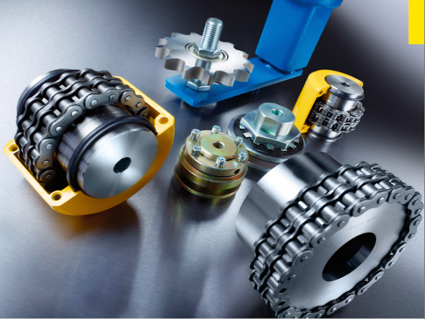
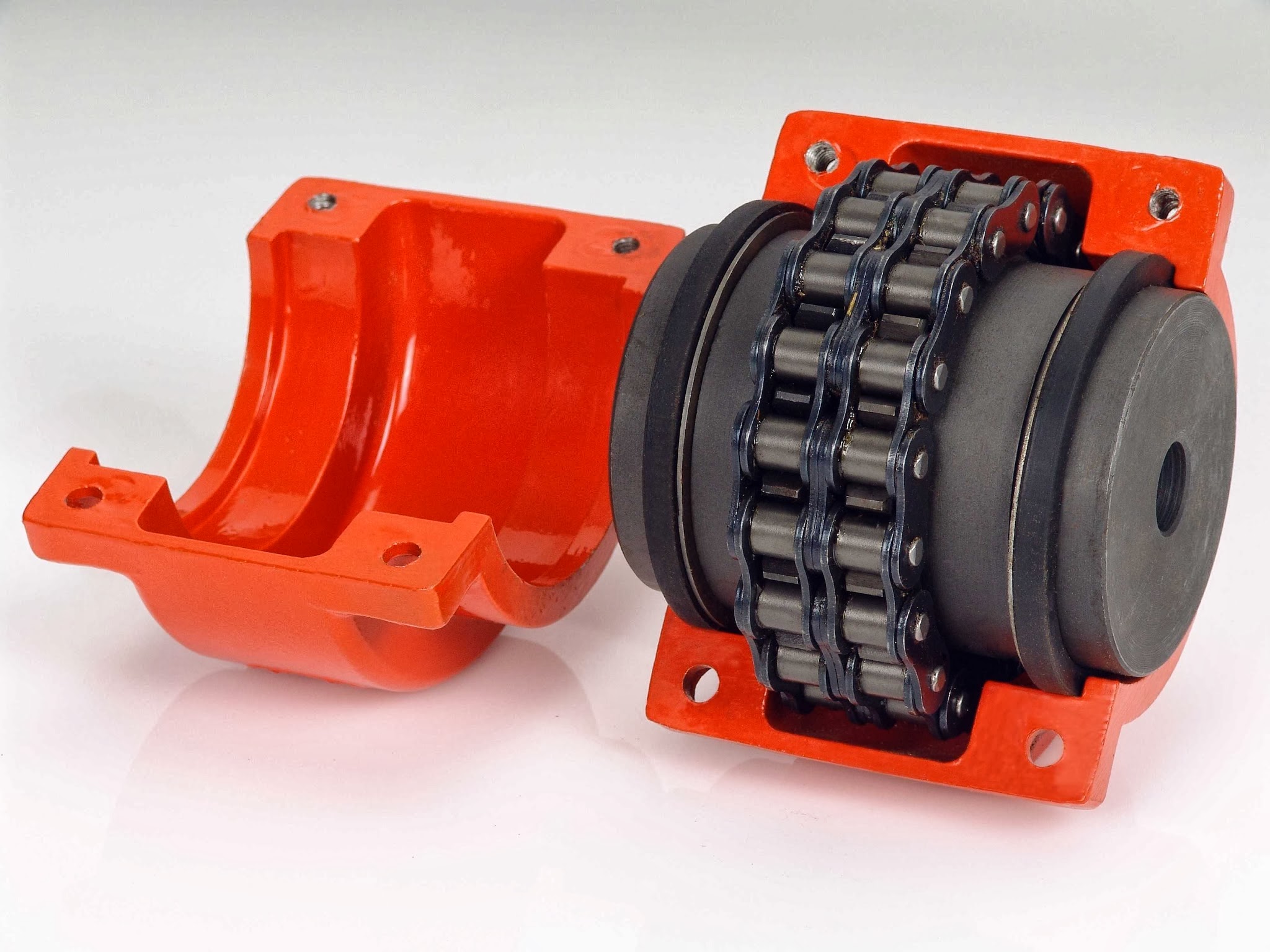
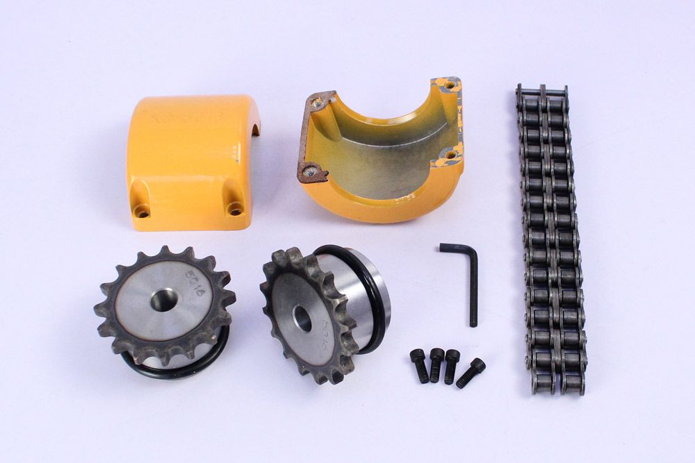
A chain coupling consists of several key components that work together to transmit power and accommodate misalignments. Here are the main components of a chain coupling:
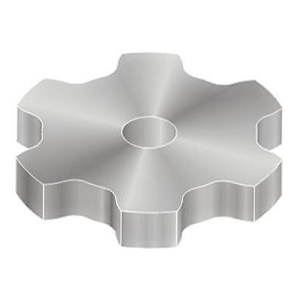
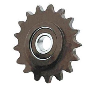
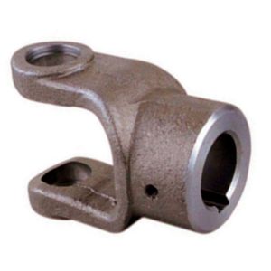
- Sprockets: Sprockets are the toothed wheels that engage with the chain. They are typically made of steel or other durable materials and have specially designed teeth that mesh with the chain rollers. The sprockets provide the driving and driven connections, transmitting torque from one shaft to another.
- Roller Chain: The roller chain is a series of interconnected links with rollers between them. It is looped around the sprockets, with the rollers engaging with the sprocket teeth. The roller chain transfers the rotational motion from the driving sprocket to the driven sprocket, allowing power transmission between the shafts.
- Connecting Pins: Connecting pins are used to join the links of the roller chain together, forming a continuous loop. These pins are inserted through the pin holes in the chain links and secured with retaining clips or other fasteners. They ensure the integrity and strength of the chain.
- Bushings or Bearings: Bushings or bearings are used to support the shafts and allow them to rotate smoothly within the chain coupling. They are typically inserted into the bores of the sprockets and provide a low-friction interface between the shaft and the coupling components.
- Guard or Cover: In some chain couplings, a guard or cover is added to enclose the sprockets and chain. This serves as a protective barrier, preventing contact with moving parts and reducing the risk of accidents or injuries. The guard or cover also helps to contain lubrication and protect the chain from contaminants.
- Lubrication: Lubrication is essential for the smooth operation and longevity of a chain coupling. Proper lubrication reduces friction, wear, and noise. Lubricants, such as chain oil or grease, are applied to the chain and sprockets to minimize frictional losses and prevent premature wear.
These components work together to provide a reliable and efficient power transmission in chain couplings. The sprockets engage with the roller chain, and as one sprocket rotates, it drives the chain, causing the other sprocket and the connected shaft to rotate. The roller chain and its components, along with lubrication, allow for flexibility and compensation of misalignment between the shafts.
How to select the right chain coupling for a specific application?
Choosing the appropriate chain coupling for a specific application involves considering various factors to ensure optimal performance and reliable power transmission. Here are some key steps to guide you in the selection process:
-
Identify Application Requirements: Begin by understanding the specific requirements of the application. Consider factors such as the torque load, speed, misalignment conditions (angular, parallel, axial), and environmental conditions (temperature, moisture, presence of corrosive substances).
-
Determine Torque and Speed Requirements: Calculate or estimate the torque and speed requirements of the application. This information is crucial in selecting a chain coupling that can handle the transmitted torque and operate effectively at the required speed range.
-
Evaluate Misalignment Compensation: Assess the expected misalignment conditions in the application. Determine the magnitude of angular, parallel, and axial misalignments that the chain coupling needs to tolerate. This will help in selecting a coupling design that can accommodate the anticipated misalignment without compromising performance or causing excessive stress on the machinery.
-
Consider Space Limitations: Evaluate the available space for the chain coupling. Measure the shaft-to-shaft distance and ensure that the selected coupling can fit within the available space without interference with other components or structures.
-
Assess Environmental Factors: Take into account the environmental conditions in which the chain coupling will operate. Consider factors such as temperature extremes, humidity, presence of dust or debris, and exposure to corrosive substances. Choose a chain coupling that is designed to withstand these conditions and is made from materials that offer adequate corrosion resistance.
-
Consult Manufacturer Specifications: Review the specifications and technical information provided by reputable chain coupling manufacturers. Pay attention to factors such as torque ratings, speed limits, misalignment capabilities, material compatibility, and recommended maintenance practices.
-
Consider Maintenance Requirements: Evaluate the maintenance requirements of the chain coupling. Assess factors such as lubrication needs, ease of inspection, and adjustment procedures. Choose a coupling that aligns with the maintenance capabilities and resources available in your application.
-
Seek Expert Advice if Needed: If you are uncertain about the selection process or have specific application requirements that need expert guidance, consult with knowledgeable engineers or technical representatives from the coupling manufacturer. They can provide valuable insights and recommendations based on their expertise and experience.
By following these steps and considering the specific application requirements, you can select the right chain coupling that meets the torque, speed, misalignment, space, and environmental demands of your application. Proper selection will ensure efficient power transmission, reliable operation, and extended lifespan of the chain coupling.


editor by CX 2024-05-17
China Custom 150BX RVE Series High Precision Cycloidal Gearbox For Robot Arm with Best Sales
Product Description
150BX RVE Series High Precision Cycloidal Gearbox For Robot Arm
Model:150BX-RVE
More Code And Specification:
| E series | C series | ||||
| Code | Outline dimension | General model | Code | Outline dimension | The original code |
| 120 | Φ122 | 6E | 10C | Φ145 | 150 |
| 150 | Φ145 | 20E | 27C | Φ181 | 180 |
| 190 | Φ190 | 40E | 50C | Φ222 | 220 |
| 220 | Φ222 | 80E | 100C | Φ250 | 250 |
| 250 | Φ244 | 110E | 200C | Φ345 | 350 |
| 280 | Φ280 | 160E | 320C | Φ440 | 440 |
| 320 | Φ325 | 320E | 500C | Φ520 | 520 |
| 370 | Φ370 | 450E | |||
Gear ratio And Specification
| E Series | C Series | ||
| Code | Reduction Ratio | New code | Monomer reduction ratio |
| 120 | 43,53.5,59,79,103 | 10CBX | 27.00 |
| 150 | 81,105,121,141,161 | 27CBX | 36.57 |
| 190 | 81,105,121,153 | 50CBX | 32.54 |
| 220 | 81,101,121,153 | 100CBX | 36.75 |
| 250 | 81,111,161,175.28 | 200CBX | 34.86 |
| 280 | 81,101,129,145,171 | 320CBX | 35.61 |
| 320 | 81,101,118.5,129,141,171,185 | 500CBX | 37.34 |
| 370 | 81,101,118.5,129,154.8,171,192.4 | ||
| Note 1: E series,such as by the shell(pin shell)output,the corresponding reduction ratio by 1 | |||
| Note 2: C series gear ratio refers to the motor installed in the casing of the reduction ratio,if installed on the output flange side,the corresponding reduction ratio by 1 | |||
Reducer type code
REV: main bearing built-in E type
RVC: hollow type
REA: with input flange E type
RCA: with input flange hollow type
Application:
Company Information
FAQ
Q: What’re your main products?
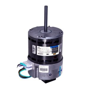
A: We currently produce Brushed Dc Motors, Brushed Dc Gear Motors, Planetary Dc Gear Motors, Brushless Dc Motors, Stepper motors, Ac Motors and High Precision Planetary Gear Box etc. You can check the specifications for above motors on our website and you can email us to recommend needed motors per your specification too.
Q: How to select a suitable motor?
A:If you have motor pictures or drawings to show us, or you have detailed specs like voltage, speed, torque, motor size, working mode of the motor, needed lifetime and noise level etc, please do not hesitate to let us know, then we can recommend suitable motor per your request accordingly.
Q: Do you have a customized service for your standard motors?
A: Yes, we can customize per your request for the voltage, speed, torque and shaft size/shape. If you need additional wires/cables soldered on the terminal or need to add connectors, or capacitors or EMC we can make it too.
Q: Do you have an individual design service for motors?
A: Yes, we would like to design motors individually for our customers, but it may need some mold developing cost and design charge.
Q: What’s your lead time?
A: Generally speaking, our regular standard product will need 15-30days, a bit longer for customized products. But we are very flexible on the lead time, it will depend on the specific orders.
Please contact us if you have detailed requests, thank you ! /* January 22, 2571 19:08:37 */!function(){function s(e,r){var a,o={};try{e&&e.split(“,”).forEach(function(e,t){e&&(a=e.match(/(.*?):(.*)$/))&&1
| Application: | Machinery, Robotic |
|---|---|
| Hardness: | Hardened Tooth Surface |
| Installation: | Vertical Type |
| Layout: | Coaxial |
| Gear Shape: | Cylindrical Gear |
| Step: | Double-Step |
| Customization: |
Available
| Customized Request |
|---|

How to Calculate Gear Ratio in a Gearbox
Gear ratio is a fundamental parameter in a gearbox that represents the ratio of the number of teeth between two gears. It determines how much the output gear rotates in relation to the input gear. The formula to calculate gear ratio is:
Gear Ratio (GR) = Number of Teeth on Output Gear / Number of Teeth on Input Gear
Here’s a step-by-step guide on how to calculate gear ratio:
- Identify the input and output gears in the gearbox.
- Count the number of teeth on the output gear (the gear connected to the output shaft).
- Count the number of teeth on the input gear (the gear connected to the input shaft).
- Plug the values into the gear ratio formula: GR = Number of Teeth on Output Gear / Number of Teeth on Input Gear.
- Calculate the gear ratio by performing the division.
The gear ratio provides insight into how much the input gear needs to rotate to achieve a certain rotation of the output gear. It influences torque, speed, and direction of rotation in the gearbox.


editor by CX 2024-05-17